
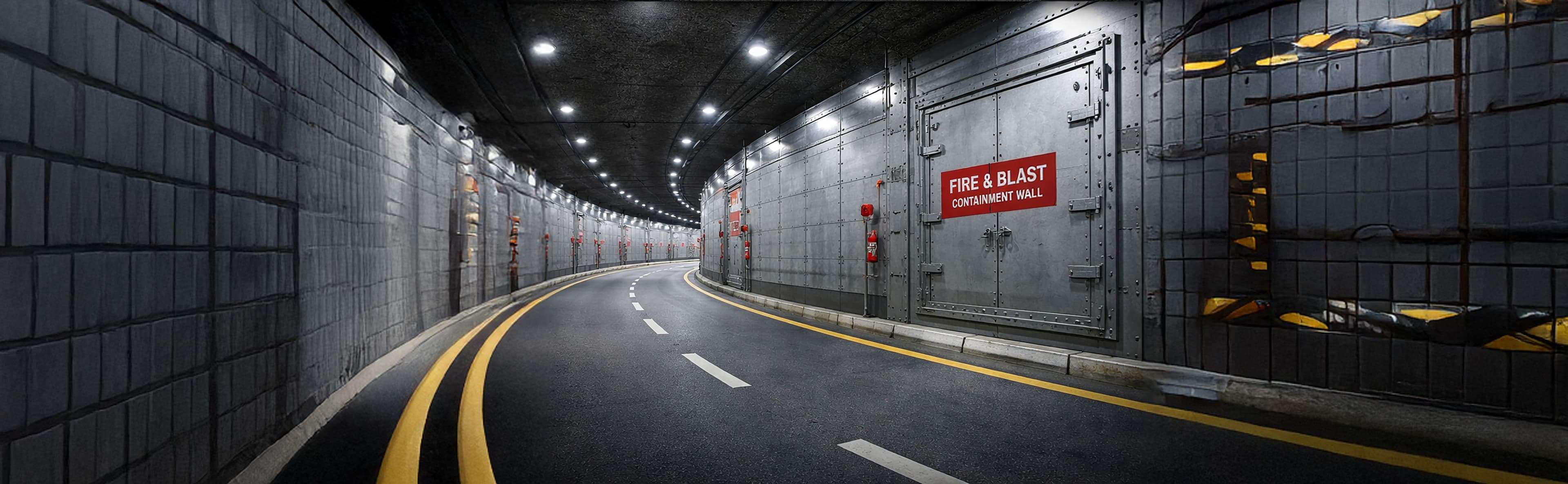


Why Transformer Fire and Blast Protection Matters
Transformer faults can involve fire, burning insulating liquid, radiant heat, pressure effects and debris. The consequences depend on the transformer type, arrangement, drainage, separation and nearby equipment. A transformer fire barrier system must therefore be selected from a project hazard assessment and coordinated with bunds, cable trenches, gates, foundations and maintenance clearances.
What is Transformer Fire & Explosion Protection
It is an engineered separation system positioned between a transformer hazard and adjacent assets or occupied areas. Its required functions may include fire separation, radiant-heat shielding and, where specifically designed and evidenced, response to defined pressure or debris effects.

Fire Containment
The barrier is positioned and detailed to limit fire exposure between the assessed transformer hazard and adjacent equipment, buildings or access areas.

Blast & Overpressure Resistance
Pressure resistance is considered only where an overpressure scenario is defined and the proposed panels, supports and connections are engineered for it.

Thermal & Radiant Heat Protection
Barrier geometry and construction are reviewed in relation to radiant-heat exposure and the assets or routes requiring protection.

Oil Spill & Projectile Resistance
Bunds, drainage and oil-management provisions are coordinated with the barrier; projectile resistance is included only where the project assessment requires it.

Fire Spread Prevention
Barrier height, length, position and interfaces are coordinated to reduce the potential for fire to affect neighbouring assets.

How the System Protects Your Facility
Invicta ANARA develops transformer fire and explosion protection barriers from the hazard basis, asset layout and required separation outcome. The complete design is coordinated with civil, structural, electrical and operational interfaces before the proposed configuration is confirmed.
The barrier build-up and extent are selected against the defined transformer fire scenario and the evidence relevant to the proposed configuration.
Where overpressure is a project requirement, panels, supports, fixings and foundations are engineered for the stated design basis.
Any requirement relating to impact or debris is assessed against the defined hazard and supported for the proposed arrangement.
A modular arrangement can support new-build or retrofit work, subject to access, structural conditions, energised-asset constraints and equipment replacement needs.

Performance & Technical Specifications
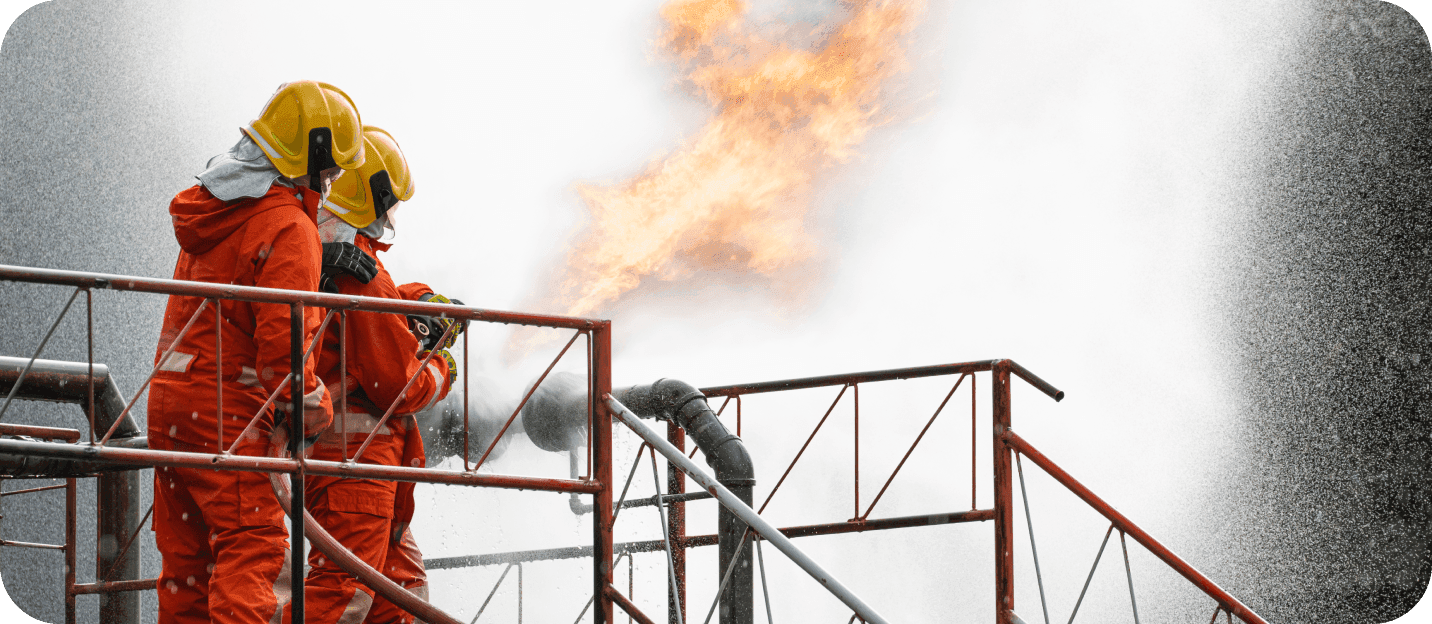
Fire & Thermal Protection
Define the fire exposure and separation objective from the transformer hazard assessment.
Coordinate barrier height, length and position with adjacent transformers, buildings and access areas.
Review fire-performance evidence for the proposed barrier assembly, orientation and interfaces.

Smoke & Gas Containment
Coordinate panel joints, perimeters and openings where the fire strategy requires control of smoke or hot-gas paths.
Review gates, doors and service penetrations as part of the complete barrier boundary.
Consider adjoining personnel routes or occupied areas when developing the interface details.

Blast & Impact Resistance
Define pressure, impact or debris requirements only where they are identified by the project hazard assessment.
Coordinate panels, supports, connections and foundations for the stated mechanical loads.
Review evidence or engineering applicable to the proposed barrier arrangement and design scenario.

Materials & Construction
Select materials and finishes for the environmental and operational conditions at the transformer installation.
Coordinate the barrier construction with foundations, bunds, drainage, cable trenches and electrical clearances.
Plan installation, inspection, repair and component replacement around site-access and operational constraints.
Engineered Transformer Barriersvs Generic Separation Walls
Traditional Methods
May not reflect the transformer-specific hazard assessment.
Can overlook bunds, drainage, trenches and electrical clearances.
May use unverified assumptions for pressure or debris resistance.
Can obstruct inspection, lifting or future transformer replacement.
Engineered Transformer Barrier System
Geometry is based on the assessed hazard and adjacent assets.
Civil, structural and electrical interfaces are coordinated together.
Any pressure-response requirement is defined and evidenced for the project.
Access, maintenance and replacement strategy inform the final layout.
Sectors We Serve
We partner with you to deliver reliable, purpose-built infrastructure that supports your goals and performs where it matters most.

Energy & Utilities

Energy & Utilities
- Power & Grid Infrastructure
- Energy & Process Facilities
- Onshore & Offshore Assets
- Renewable Energy Infrastructure

Industrial
Industrial
- Chemical & Process Plants
- Manufacturing & Heavy Industry
- Hazardous Material storage facilities
- Automotive & Industrial Campuses

Transportation
Transportation
- Airports & Aviation Facilities
- Metro, Rail & Mass Transit Systems
- Roads, Highways & Vehicular Tunnels
- Ports, Shipyards & Marine Transport Infrastructure

Defence
Defence
- Defence & Command Facilities
- Critical National Infrastructure (CNI)
- Secure & Hardened Assets
- Border, Coastal & Strategic Installations

Infrastructure
Infrastructure
- Data Centres & Digital Infrastructure
- Public Venues & Stadia
- Cultural & Institutional Buildings
- Government & Diplomatic Facilities

Commercial/Mixed-Use
Commercial/Mixed-Use
- Hospitality & Leisure
- Financial & Commercial Buildings
- Mixed-Use Landmark Developments



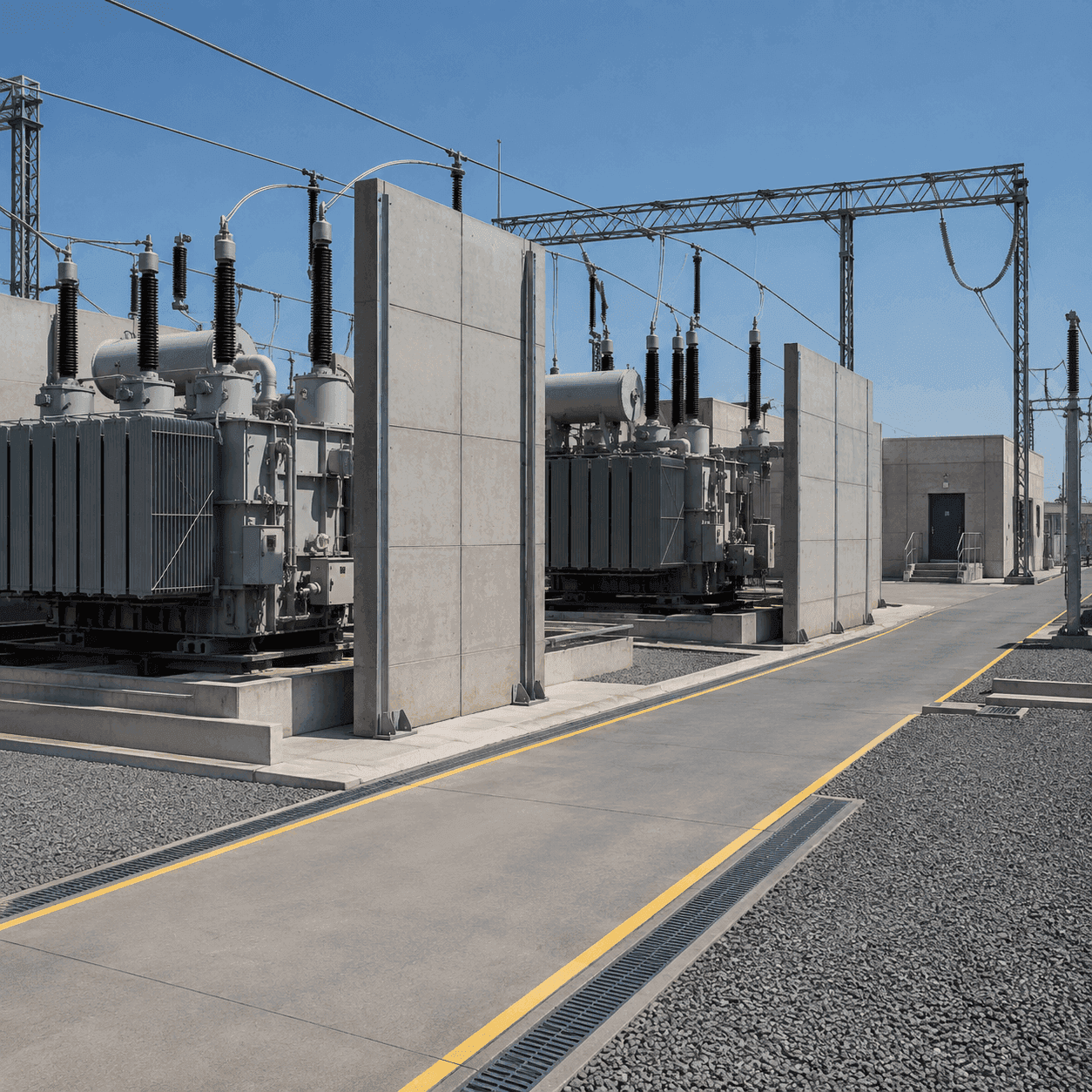
Where Transformer Protection Barriers Are Applied
Barrier requirements are considered where a transformer fire or project-defined pressure event could affect neighbouring assets, buildings or access areas. The final scope follows the asset layout and hazard assessment.
Between adjacent transformers
Between transformers and buildings
Around access and operational routes
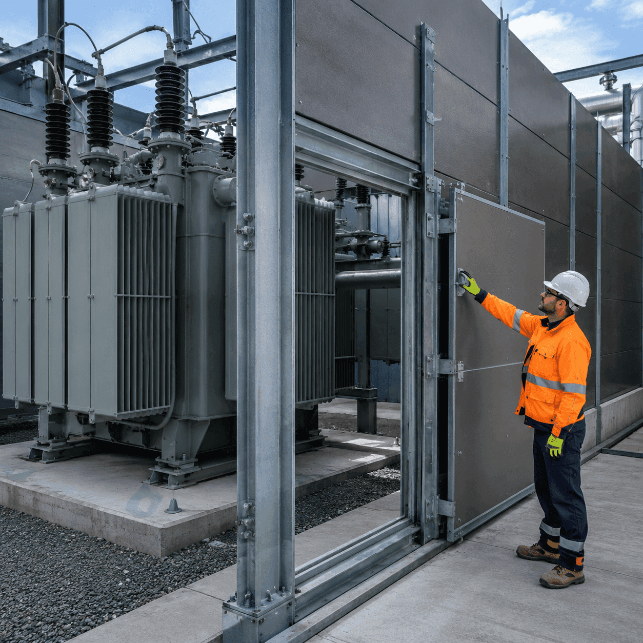
Access and Demountability Considerations
Transformer barriers must support the required separation objective without preventing inspection, maintenance or future equipment replacement.
Inspection and maintenance clearances
Gates and removable provisions
Replacement and lifting routes
What Transformer Fire and Explosion Protection Barriers Must Address
Evaluate the complete installed system against the project design basis, interfaces and evidence—not as an isolated product selection.
Define the transformer arrangement, credible fire scenario, adjacent assets and required separation outcome.
Project risk and purpose
Coordinate foundations, bunds, drainage, cable trenches, gates, clearances and maintenance access.
Critical interfaces
Review fire, structural and any applicable pressure-response evidence against the actual barrier design.
Evidence-led selection
Inputs for Specifying Transformer Fire and Explosion Protection Barriers
A clear technical review begins with the performance basis and the conditions the installed system will encounter.
Transformer arrangement and hazard study
Provide transformer type, insulating medium, layout, adjacent equipment and credible event scenarios.
Fire and overpressure scenarios
State the required fire-separation outcome and any specifically assessed overpressure or debris criteria.
Barrier geometry and separation distances
Confirm height, length, position, foundations, bunds, trenches, drainage and penetrations.
Drainage, access and maintenance strategy
Define inspection access, gates, clearances, lifting routes and transformer replacement needs.
Frequently Asked Questions About Transformer Fire and Explosion Protection Barriers
Direct answers to common specification, coordination and evidence questions.
Provide the transformer type and insulating medium, site layout, adjacent assets, separation distances, credible fire scenario, and any project-defined pressure or debris criteria. Include civil, structural and electrical drawings together with access, drainage and equipment-replacement requirements.
Coordinate the barrier line with the foundations, bunds, drainage, cable trenches, clearances, gates and access routes. Panels, supports, fixings and openings should be reviewed as one arrangement so adjoining systems do not interrupt the intended separation or obstruct operation.
Review the transformer hazard assessment, fire-performance evidence relevant to the proposed assembly, approved drawings and structural information. Where pressure, impact or debris resistance is required, review project-applicable engineering or evidence for the barrier, supports, connections and foundations.
Develop the barrier line with the oil-containment, drainage and cable-routing strategy. Trenches, penetrations and changes in level require coordinated details that maintain the intended separation and structural continuity.
A retrofit may be possible after surveying foundations, clearances, trenches, access and operational constraints. Installation sequencing and future transformer-replacement routes should be resolved before the configuration is approved.
Demountable sections, gates or removable provisions may be considered where inspection or equipment replacement requires them. Their interfaces, supports and closures must be coordinated with the barrier system and the evidence applicable to the required performance.