
Why the Tested Assembly Matters More Than a Single Fire-Rated Material
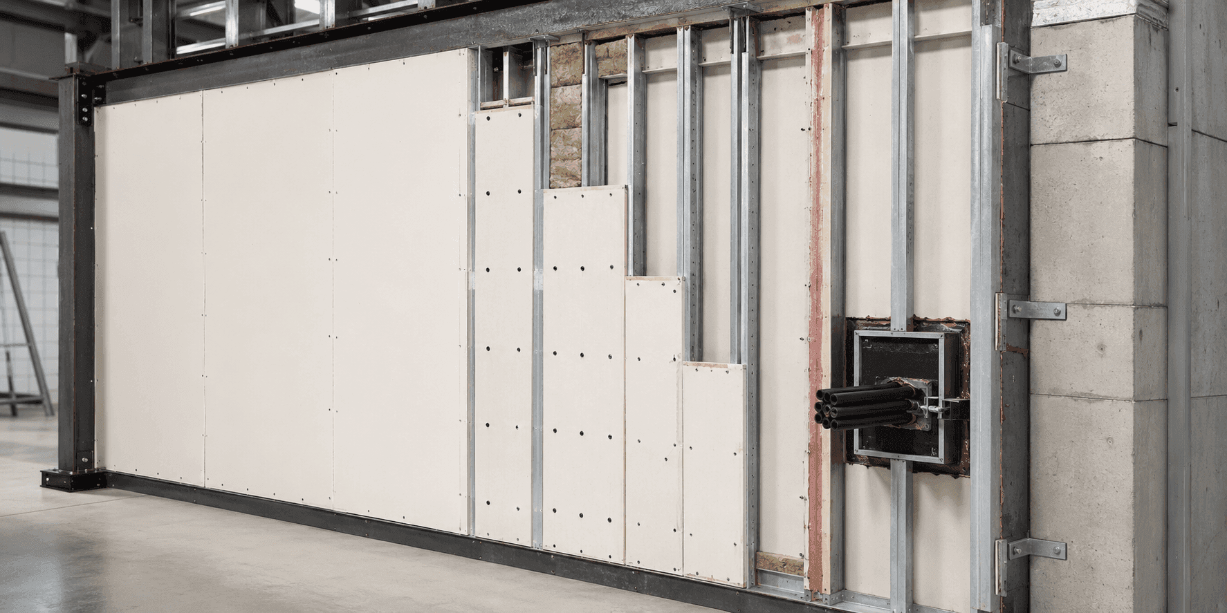
A tested fire-rated assembly combines materials, supports, fixings, joints and interfaces in a defined configuration. One fire-rated material cannot establish the performance of a complete wall, ceiling, floor, duct or enclosure by itself.
What Is a Tested Fire-Rated Assembly?
A tested fire-rated assembly is the complete specimen evaluated against defined fire-resistance criteria. It can include protective boards or panels, framing, insulation, fixings, joint treatments, supports, edge details and any openings represented in the evidence.
Materials contribute important properties, but assembly behaviour depends on how they are combined. Heat can affect fixings, framing can expand or deflect, joints can open, and unsupported edges can behave differently from the central area. The substrate and restraint can also influence the result.
For this reason, project teams should compare the intended construction with the tested or assessed configuration. Substituting one component, altering spacing or adding an unrepresented penetration may move the installation outside the available evidence.
- Protective layer: Boards, panels, coatings or other materials used in the tested arrangement.
- Framing and supports: Members, substrates and restraint conditions that carry and stabilise the assembly.
- Fixings: Type, size, spacing, edge distance and installation pattern represented by the evidence.
- Joints: Seams, seals, overlaps and movement details that preserve continuity.
- Openings: Doors, ducts, pipes, cables and other penetrations included or permitted.
- Orientation and exposure: The direction, position and fire side for which the assembly was evaluated.
Fire-Rated Material Compared with a Tested Assembly
- Meaning: A material has stated properties or evidence within a particular use. An assembly demonstrates defined performance as a complete configuration.
- Scope: Limited to the component and stated conditions. Includes interacting supports, fixings, joints and interfaces.
- Selection: Useful input when choosing a system. Primary basis for matching the complete project arrangement.
- Modification: A similar material may still behave differently in the system. Changes require confirmation within the evidence or technical assessment.
- Inspection: Confirms product identity and condition. Also checks layout, spacing, joints, edges, openings and supports.
How Assembly Components Work Together
Fire resistance is created by the combined behaviour of the system rather than by one visible layer.
- Layers manage heat exposure: The arrangement and thickness of materials contribute to the required criteria.
- Framing transfers load: Supports maintain geometry and stability as temperatures and movement change.
- Fixings retain components: Spacing and embedment help keep protective layers in their intended position.
- Joints accommodate interfaces: Seams and movement details limit openings through the boundary.
- Edges connect to construction: Head, base and side details complete the assembly at surrounding elements.
- Penetrations preserve function: Approved opening systems maintain the required boundary around services.
Changes That Can Invalidate an Assumption
A change does not have to appear large to affect the behaviour represented by the evidence.
- Different fixing pattern: Increased spacing or substituted fixings alter retention and support.
- Changed substrate: The assembly is connected to construction not covered by the evidence.
- Unapproved penetration: A service or opening interrupts layers, framing or joint details.
- Greater dimensions: Height, span or unsupported area exceeds the permitted application.
- Reversed orientation: The fire exposure or system direction differs from the evaluated arrangement.
Benefits of Assembly-Based Specification
Specifying the complete system improves clarity across design, procurement, installation and inspection.
- Defined scope: All critical components and interfaces are visible.
- Relevant evidence: The project arrangement can be compared with documented limitations.
- Controlled substitutions: Changes are assessed against their role in the system.
- Better inspection: Site teams can verify more than product labels.
What Should Project Teams Verify?
Verification should connect the evidence, approved drawings and installed work.
- Are all components identified?: Confirm materials, framing, fixings, joints and accessories.
- Does the support match?: Review substrates, restraint, deflection and connection details.
- Are dimensions permitted?: Check height, span, orientation and unsupported limits.
- Are openings represented?: Match doors and services to appropriate system evidence.
- Are changes traceable?: Record substitutions and reviewed deviations before close-out.
How Invicta ANARA Supports Systems-Level Infrastructure Delivery
SECURA by Invicta ANARA approaches fire-protection requirements at system level. Selection and delivery should remain tied to the complete assembly, configuration-specific evidence, coordinated interfaces and project review.
SECURA by Invicta ANARA. Explore critical containment and protection systems for relevant fire and infrastructure risks.
Fire protection systems. Review Invicta ANARA fire-protection capabilities and related applications.
Industrial fire compartmentation walls. Explore compartmentation walls planned around complete assemblies and project interfaces.
Frequently Asked Questions
Direct answers to common questions about tested fire rated assembly.
What is a tested fire-rated assembly?
It is the complete system specimen—including materials, supports, fixings and joints—evaluated against defined fire-resistance criteria.
Why is a fire-rated board not enough?
The board relies on framing, fixings, joints, edges and openings that influence complete-system behaviour.
Can one component be substituted?
Only when the applicable evidence or a competent assessment supports the change.
Do penetrations form part of the assembly?
Yes. Openings and their protection are critical interfaces and require suitable system evidence.
What should inspectors check?
They should check component identity, layout, supports, fixing spacing, joints, edges, openings, damage and recorded changes.
Share the proposed assembly, support details and openings so configuration-relevant evidence and interfaces can be reviewed. Discuss an Infrastructure Requirement.