
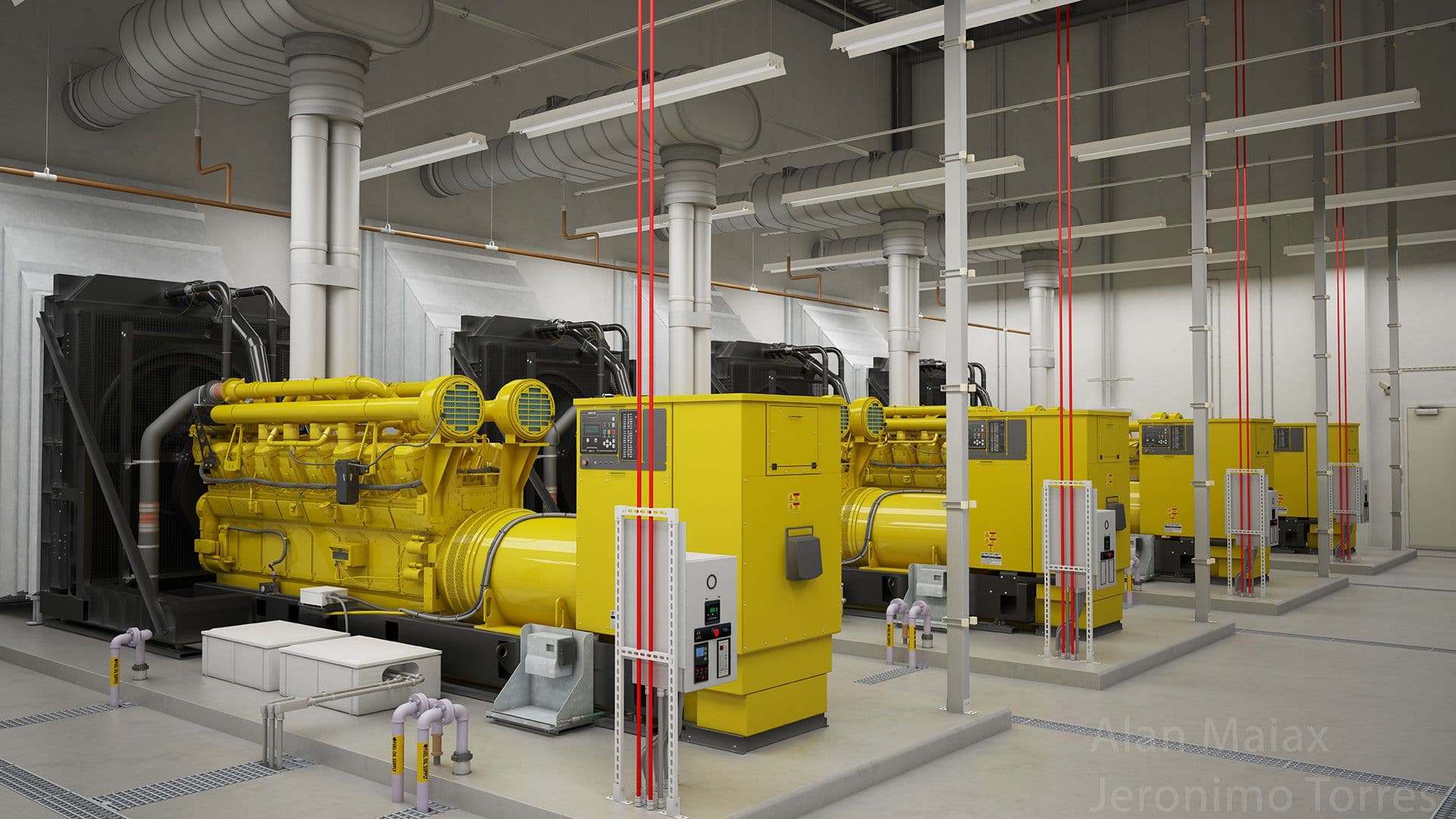
Generator Room Fire & Explosion Protection Barriers
Fire-separation wall systems for generator rooms and adjoining occupied, service or plant areas, planned around the fire strategy, room layout, essential openings, operational access and evidence required for the proposed configuration.

Why Generator Room Fire Separation Walls Matter
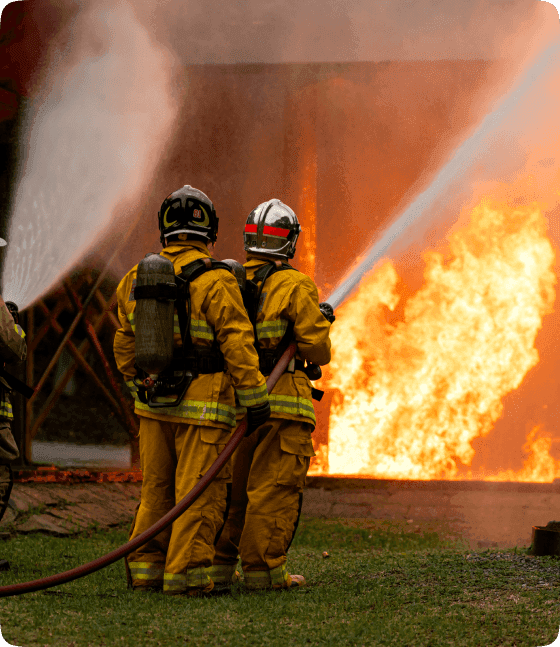
Generator rooms bring together fuel, electrical loads, heat-generating equipment and continuous mechanical operation. If a fire starts, an inadequately protected boundary can allow heat, flames and smoke to affect adjoining spaces and essential building services. A dedicated fire-separation wall helps contain the incident within the room, protect adjacent assets and support evacuation and emergency response. The complete boundary must be coordinated with doors, ventilation openings, cable and pipe penetrations, structural interfaces and maintenance access.
What is Generator Room Fire Separation Wall
A generator room fire-separation wall forms a protective boundary between the room and adjoining areas. Its performance depends on the complete installed assembly, including panels, joints, supports, openings and service penetrations—not on the wall panels alone.

Fire Resistance
The proposed wall build-up should be supported by fire-resistance evidence appropriate to the required duration, dimensions, supports and end-use conditions.

Blast Protection
Where the project risk assessment identifies overpressure, the wall, supports, fixings and interfaces should be evaluated for the defined combined hazard rather than assumed to provide blast resistance.

Thermal Shock Stability
Material behaviour, joints and fixings should remain compatible with the expected temperature exposure and heating conditions defined by the project fire scenario.

Impact & Debris Resistance
Where impact or debris is a credible project hazard, the complete assembly should be assessed against the relevant loading and acceptance criteria.

Smoke & Gas Isolation
Joints, perimeter interfaces and service penetrations require coordinated sealing to limit routes through which smoke and hot gases could migrate.

How the System Protects Your Generator Room
The system forms a continuous fire-separation boundary around the generator room. Its effectiveness depends on coordinating the wall panels with their supporting structure, joints, doors, ventilation openings and service penetrations while retaining the access needed for operation, inspection and equipment replacement.
The wall build-up is selected against the project fire strategy and the evidence available for the proposed configuration, helping restrict fire and heat transfer to adjoining areas.
Panels, supports, fixings and boundary conditions must be coordinated so the assembly can maintain the required stability for the specified fire-resistance period.
Sealed joints, perimeter details and tested penetration arrangements help limit pathways for smoke and hot gases across the separation boundary.
If overpressure is part of the defined hazard scenario, the wall and its connections require project-specific engineering and supporting evidence for the relevant loads.
A modular arrangement can support new-build or retrofit installation, subject to site access, existing structure, temporary works and the need to maintain generator-room operations.
Performance & Technical Specifications
Fire & Thermal Protection
Select the required fire-resistance performance from the approved fire strategy and project specification.
Confirm that the supporting evidence applies to the proposed wall build-up, dimensions, orientation, supports and boundary conditions.
Coordinate adjoining construction so heat exposure at interfaces does not compromise the intended separation.
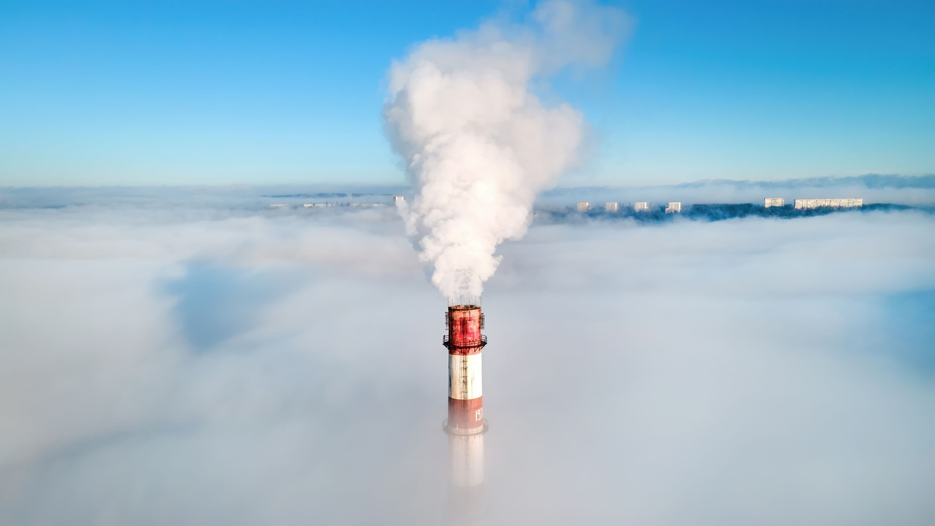
Smoke & Gas Containment
Detail panel joints, perimeters and transitions to maintain continuity across the separation boundary.
Use suitable arrangements for doors, dampers and cable, pipe or fuel-service penetrations.
Review access panels and later service changes so unplanned openings do not weaken the completed system.

Blast & Impact Resistance
Define blast, pressure or impact requirements only where they are identified by the project risk assessment.
Coordinate panels, supports and connections for the stated loads and acceptance criteria.
Review fire and mechanical performance together where a combined-hazard condition must be addressed.
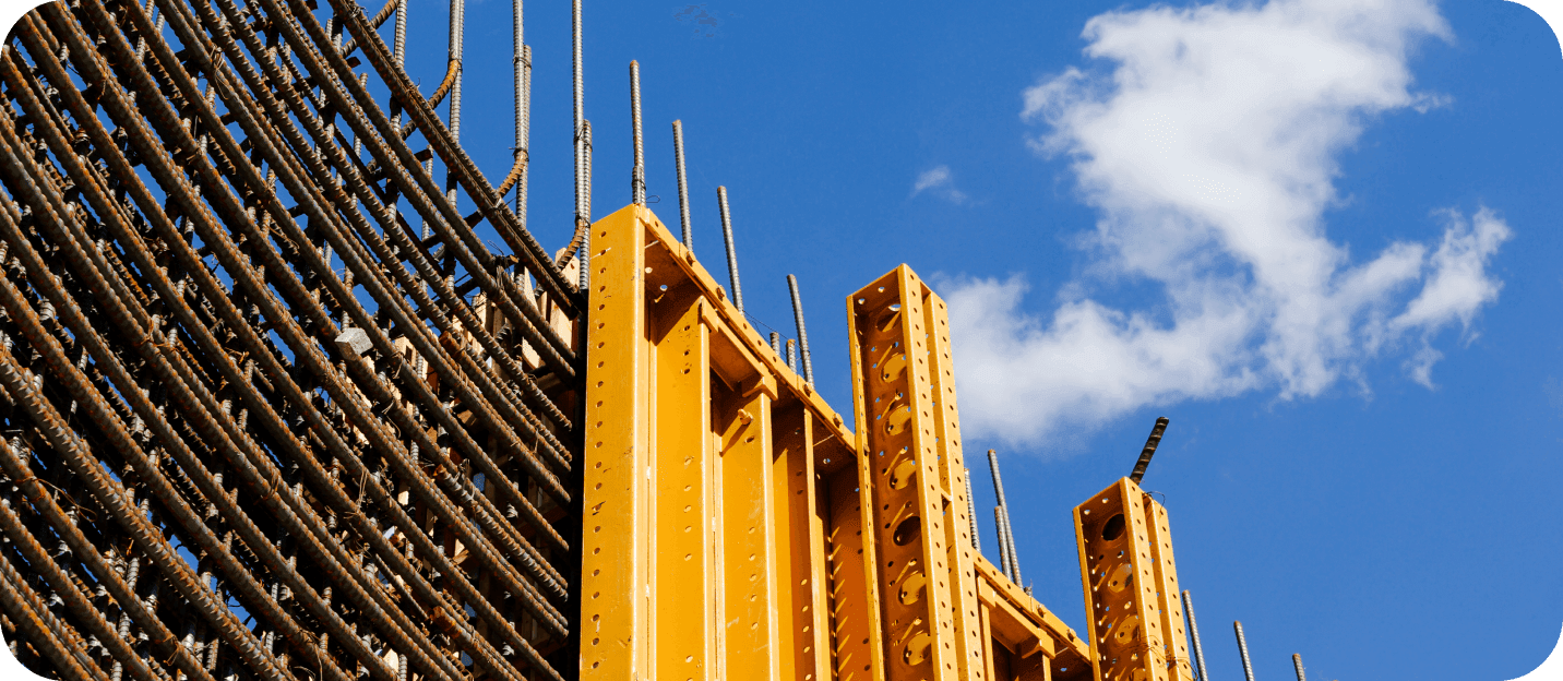
Materials & Construction
Select materials and finishes for the room environment, including moisture, corrosion and maintenance conditions.
Coordinate panel sizes and handling requirements with available access, lifting constraints and installation sequence.
Plan inspection, maintenance and equipment-replacement access without creating unreviewed breaks in the wall.
Advantages Over ConventionalGenerator Room Wall Construction
The comparison should be made at system level, considering the fire-separation requirement, interfaces, installation constraints and supporting evidence for the complete wall assembly.
Traditional Methods
Heavy construction can increase structural demand and may be difficult to introduce within an operating facility.
Wet trades or site-applied systems can extend installation and curing time, depending on the selected method and site conditions.
Openings, penetrations and later service alterations still require compatible, evidence-backed details.
Repair or equipment replacement may involve greater disruption where access has not been planned into the wall arrangement.
SECURA Generator Room Wall Benefits
Panels, supports, joints and interfaces can be developed as one coordinated fire-separation assembly.
A modular build can support planned installation and future access, subject to the approved project details.
The wall layout can be coordinated around ventilation, services and equipment-maintenance requirements.
Configuration-specific evidence can be reviewed against the proposed dimensions, supports, joints and penetrations before specification.
Sectors We Serve
Our solutions are designed for sectors where infrastructure reliability, safety, and long-term performance are critical.

Energy & Utilities

Energy & Utilities
- Power & Grid Infrastructure
- Energy & Process Facilities
- Onshore & Offshore Assets
- Renewable Energy Infrastructure
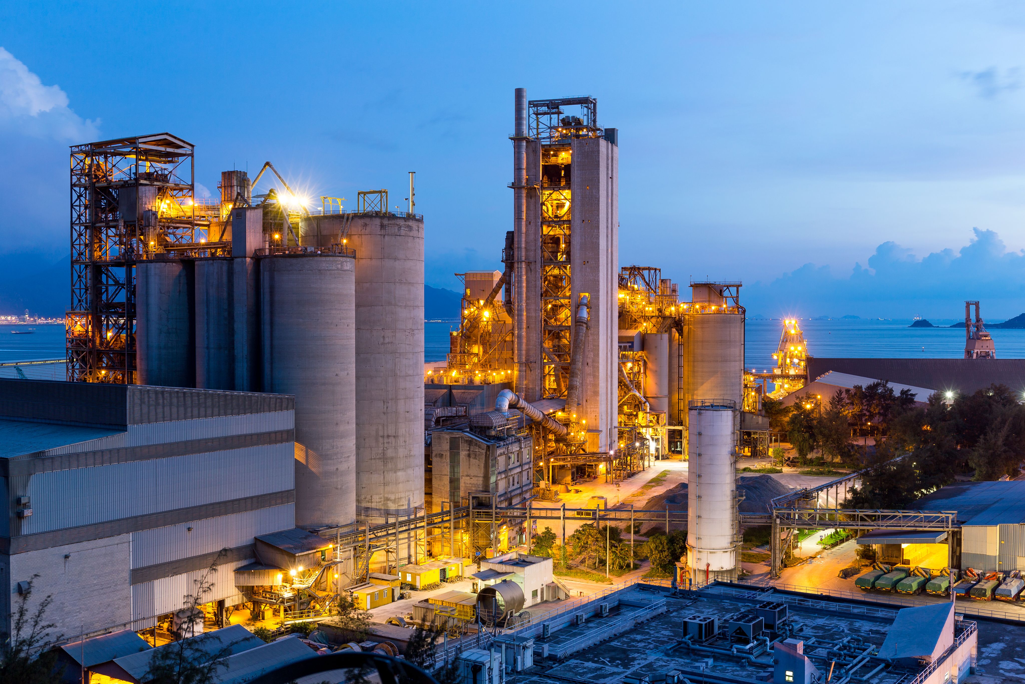
Industrial
Industrial
- Chemical & Process Plants
- Manufacturing & Heavy Industry
- Hazardous Material storage facilities
- Automotive & Industrial Campuses

Transportation
Transportation
- Airports & Aviation Facilities
- Metro, Rail & Mass Transit Systems
- Roads, Highways & Vehicular Tunnels
- Ports, Shipyards & Marine Transport Infrastructure
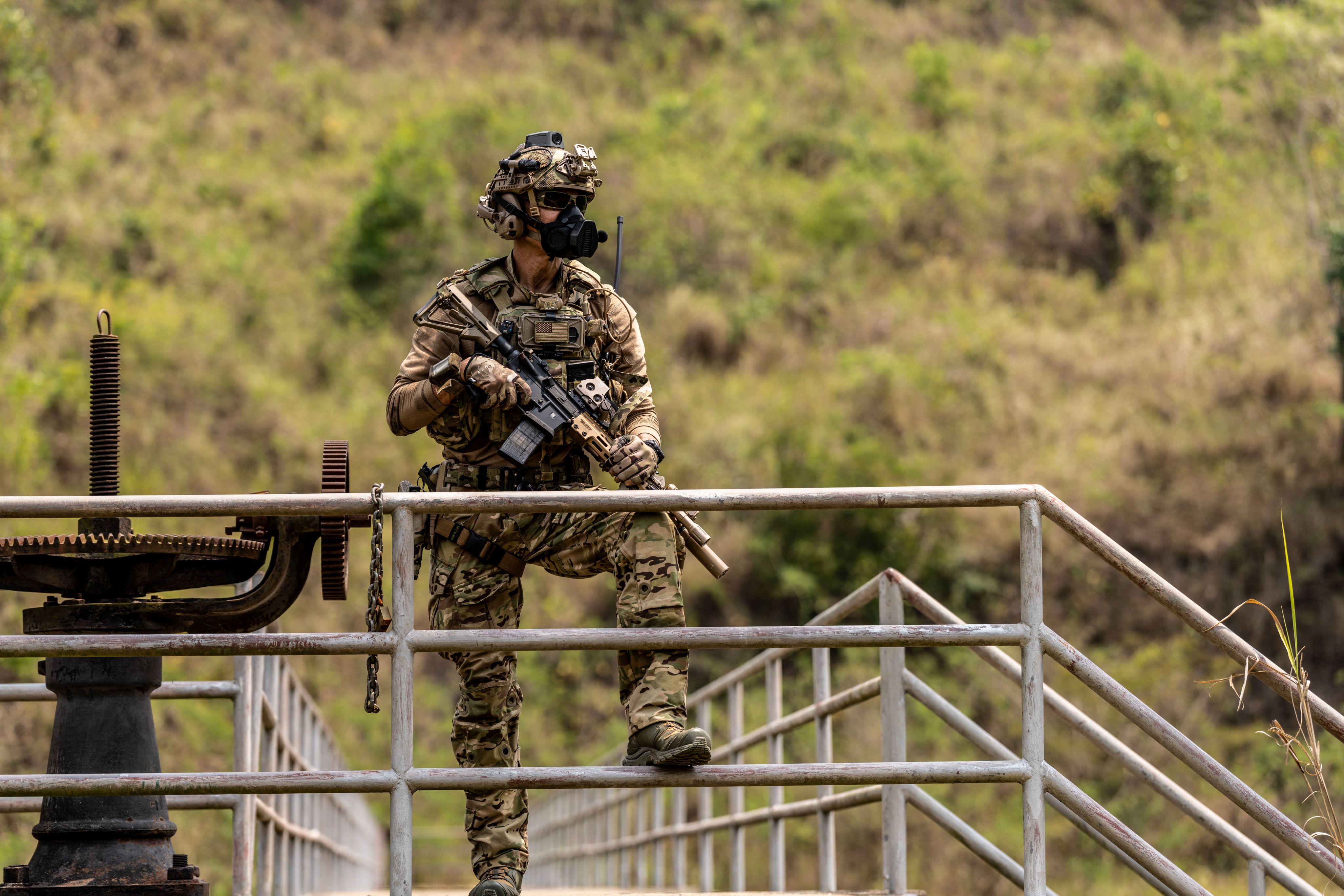
Defence
Defence
- Defence & Command Facilities
- Critical National Infrastructure (CNI)
- Secure & Hardened Assets
- Border, Coastal & Strategic Installations

Infrastructure
Infrastructure
- Data Centres & Digital Infrastructure
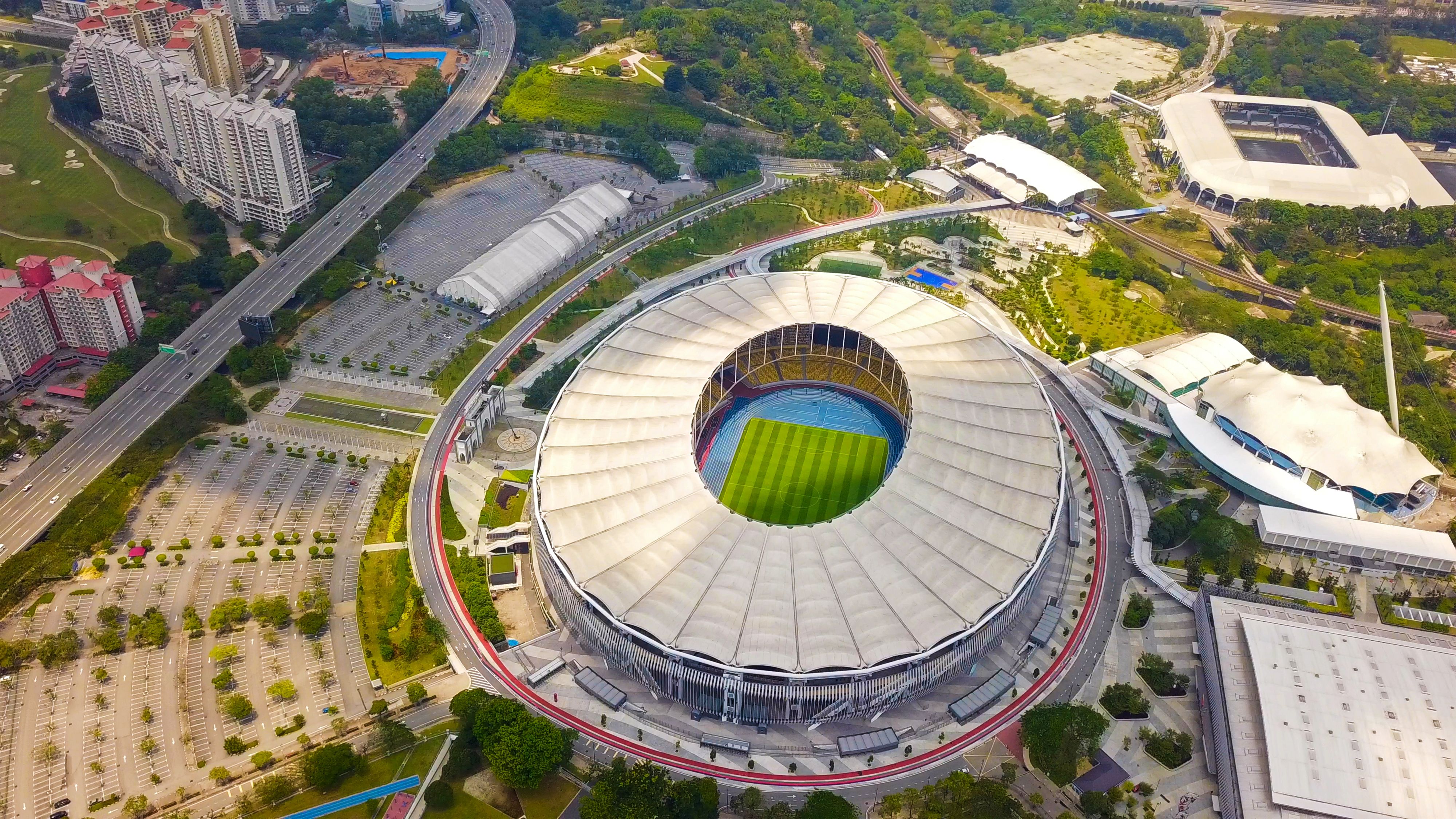
- Public Venues & Stadia
- Cultural & Institutional Buildings
- Government & Diplomatic Facilities
Commercial/Mixed-Use
Commercial/Mixed-Use
- Hospitality & Leisure
- Financial & Commercial Buildings
- Mixed-Use Landmark Developments



Where Generator Room Fire Separation Walls Are Applied
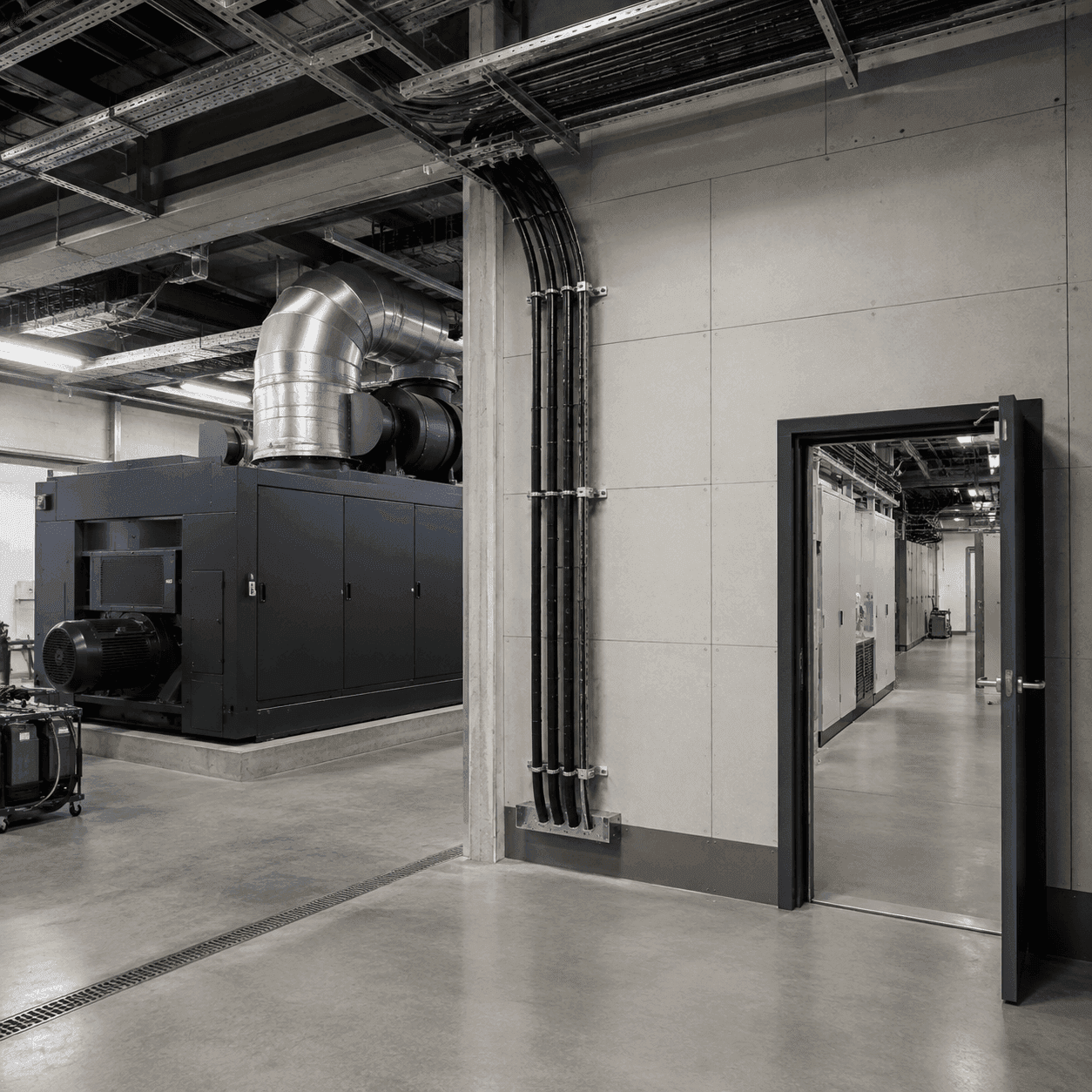
The wall arrangement is considered where a generator-room fire could affect adjoining occupied areas, essential services, plant spaces or operational routes. The required scope remains subject to the project fire strategy and room layout.
Standalone and enclosed generator rooms
Generator rooms beside critical services
Existing facilities requiring upgraded separation
New-Build and Retrofit Planning
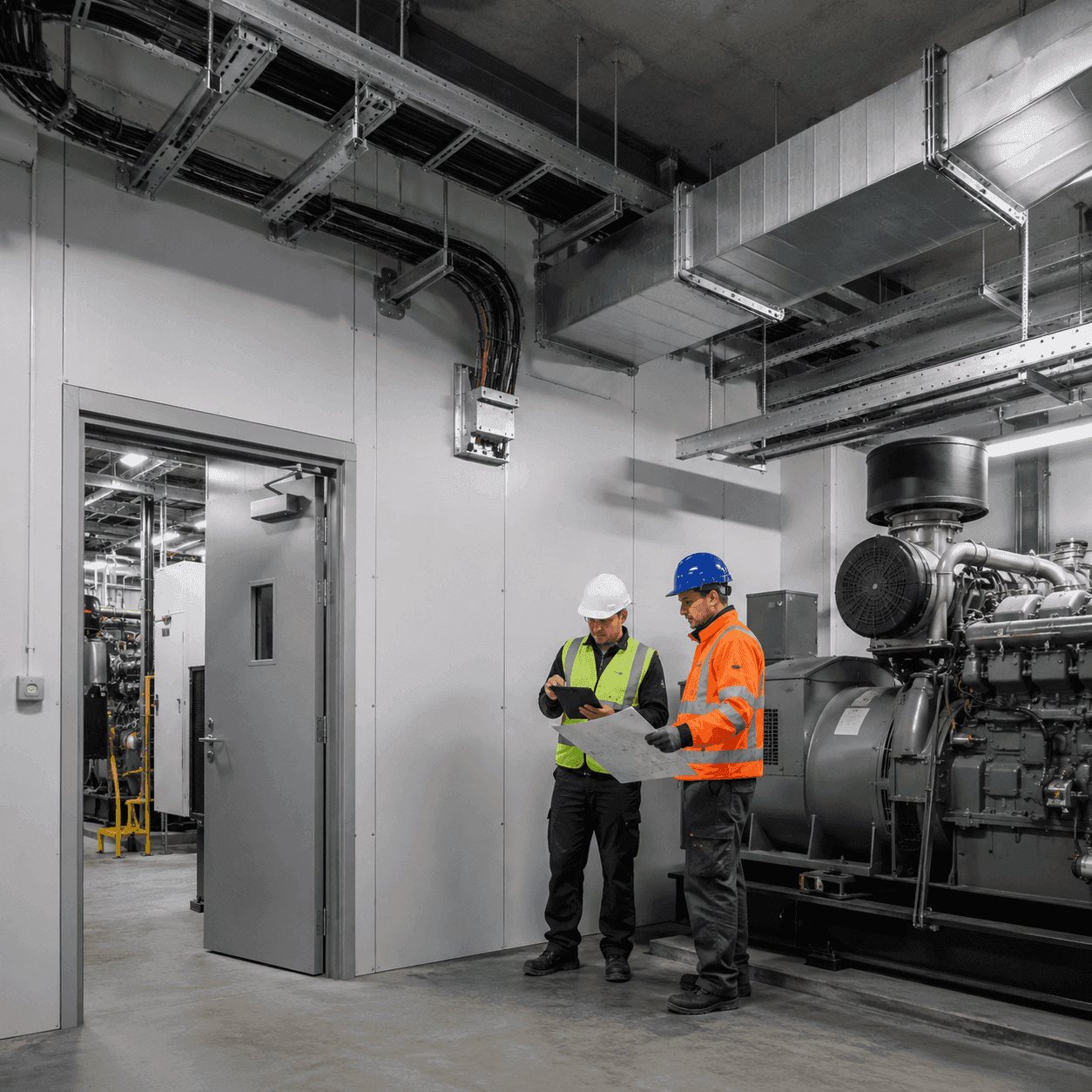
The same fire-separation objective can involve different design and installation constraints in a new facility and an operating generator room.
New-build coordination
Retrofit constraints
Equipment replacement access
What Generator Room Fire Separation Walls Must Address
Selection should consider the generator-room hazard, the complete separation boundary and the evidence needed for the proposed arrangement—not the wall panel in isolation.
Define the applicable fire scenario, required separation period, adjacent spaces and assets that the wall is intended to protect.
Project risk and purpose
Coordinate doors, ventilation openings, cable, pipe and fuel-service penetrations, wall perimeters and structural abutments as part of the complete boundary.
Critical interfaces
Check that fire-resistance evidence is relevant to the proposed wall build-up, dimensions, orientation, supports, joints and penetration details.
Evidence-led selection
Inputs for Specifying Generator Room Fire Separation Walls
A useful design brief identifies the intended performance and the physical and operational conditions that will affect the installed wall.
Fire strategy and hazard scenario
Confirm the design fire scenario, required fire-resistance performance, protected spaces and any combined hazards identified by the project team.
Room layout and wall dimensions
Provide wall height and length, support locations, boundary conditions, available space and relevant adjoining construction.
Ventilation, fuel and cable routes
Identify every planned opening and service route so compatible doors, dampers, seals and penetration details can be coordinated.
Maintenance and equipment replacement access
Define inspection routes, removable areas and equipment-replacement needs before the wall arrangement and installation sequence are finalised.
Frequently Asked Questions About Generator Room Fire Separation Walls
Answers to common questions raised during early design, specification and project coordination.
Start with the approved fire strategy, hazard scenario, required fire-resistance performance, room layout and wall dimensions. Also provide drawings showing supports, doors, ventilation, cable and pipe penetrations, fuel-service routes, adjoining construction and maintenance access.
Treat panels, supports, joints, doors, dampers, penetrations and wall perimeters as one assembly. Each interface should use a compatible detail that is appropriate to the required performance and the proposed construction.
Review evidence that applies to the proposed wall build-up, orientation, dimensions, supporting structure, joints and penetrations. A general product statement should not be assumed to cover every configuration or project condition.
A retrofit may be possible after reviewing the existing structure, available space, access, operating constraints and required interfaces. The installation sequence should also account for temporary protection and any need to keep essential equipment operational.
Openings should be identified early and coordinated with suitable doors, dampers, seals or penetration systems. Their arrangement and supporting evidence must be compatible with the wall and the project fire strategy.
Yes, where those hazards are defined by the project risk assessment. The panels, supports, fixings and interfaces then require engineering and evidence relevant to the combined loading and required acceptance criteria.