


Why Intake and Exhaust Protection Matters
Ventilation openings can provide a direct path for fan, engine and mechanical noise to leave a plantroom or enclosure. Acoustic screens must control that breakout without imposing unacceptable airflow restriction or obstructing inspection and maintenance. The final arrangement should balance acoustic targets, airflow, pressure drop, weather exposure, opening geometry and structural support.
What is an Intake and Exhaust Acoustic Screen?
An intake or exhaust acoustic screen is a ventilated noise-control assembly positioned at an air opening. It is configured to reduce sound transmission while allowing the required airflow, with geometry and materials selected around the noise spectrum, pressure-drop limits, weather conditions and maintenance needs.

Noise Attenuation
The screen arrangement is selected around the equipment noise spectrum and the target conditions at relevant receptors.

Airflow Efficiency
Free area and acoustic-path geometry are coordinated with the required intake or exhaust airflow and allowable resistance.

Weather Resistance
External arrangements account for rain, drainage, wind and the environmental exposure identified for the site.

Structural Strength
Frames, supports and opening interfaces are coordinated with the screen geometry and applicable site loads.

Easy Maintenance
Inspection, cleaning, removal and nearby equipment access are considered before the final screen layout is confirmed.

How the System Protects Your Facility
Invicta ANARA coordinates intake and exhaust acoustic screens with the equipment airflow requirement, acoustic design basis and opening geometry. The screen-to-opening interface, structural support, exposure and maintenance strategy are reviewed as part of the complete arrangement.
The screen geometry is selected around source noise data and the acoustic criteria for nearby receptors.
Free area and internal acoustic paths are coordinated with the required airflow and allowable pressure drop.
External screens are detailed for the rain, drainage and contamination conditions identified for the installation.
Materials, frames and supports are selected for the relevant environmental and structural conditions.
The arrangement allows inspection, cleaning and removal without unnecessarily obstructing adjacent equipment.
Performance & Technical Specifications
Acoustic design
Use source-spectrum data and receptor targets to define the required outcome.
Review evidence for the selected acoustic-screen arrangement.
Consider breakout around edges and adjoining construction.

Airflow performance
Confirm airflow volume, velocity and allowable pressure drop.
Coordinate free area and screen geometry with fans and ventilation systems.
Check operating conditions for both intake and exhaust applications.

Weather and structural design
Review wind loading, rain exposure, drainage and corrosion environment.
Coordinate frames, supports and opening interfaces.
Select materials and finishes for the actual site conditions.

Access and maintenance
Plan inspection, cleaning and removal access.
Avoid obstructing dampers, filters or equipment service zones.
Document the installed arrangement for later maintenance or replacement.
Engineered Acoustic Screensvs Uncoordinated Ventilation Screens
Traditional Methods
May be selected without source-spectrum or receptor criteria.
Can add pressure drop without checking the equipment duty.
Edge gaps and opening interfaces may allow noise breakout.
Weather, drainage and maintenance access may be addressed late.
Engineered Intake or Exhaust Acoustic Screen
Balances acoustic attenuation with defined airflow limits.
Geometry is coordinated with opening size, direction and mechanical duty.
Frames, seals and surrounding construction are reviewed together.
Exposure, drainage and service access inform the final arrangement.
Sectors We Serve
Our solutions are designed for sectors where infrastructure reliability, safety, and long-term performance are critical.

Energy & Utilities

Energy & Utilities
- Power & Grid Infrastructure
- Energy & Process Facilities
- Onshore & Offshore Assets
- Renewable Energy Infrastructure
Industrial
Industrial
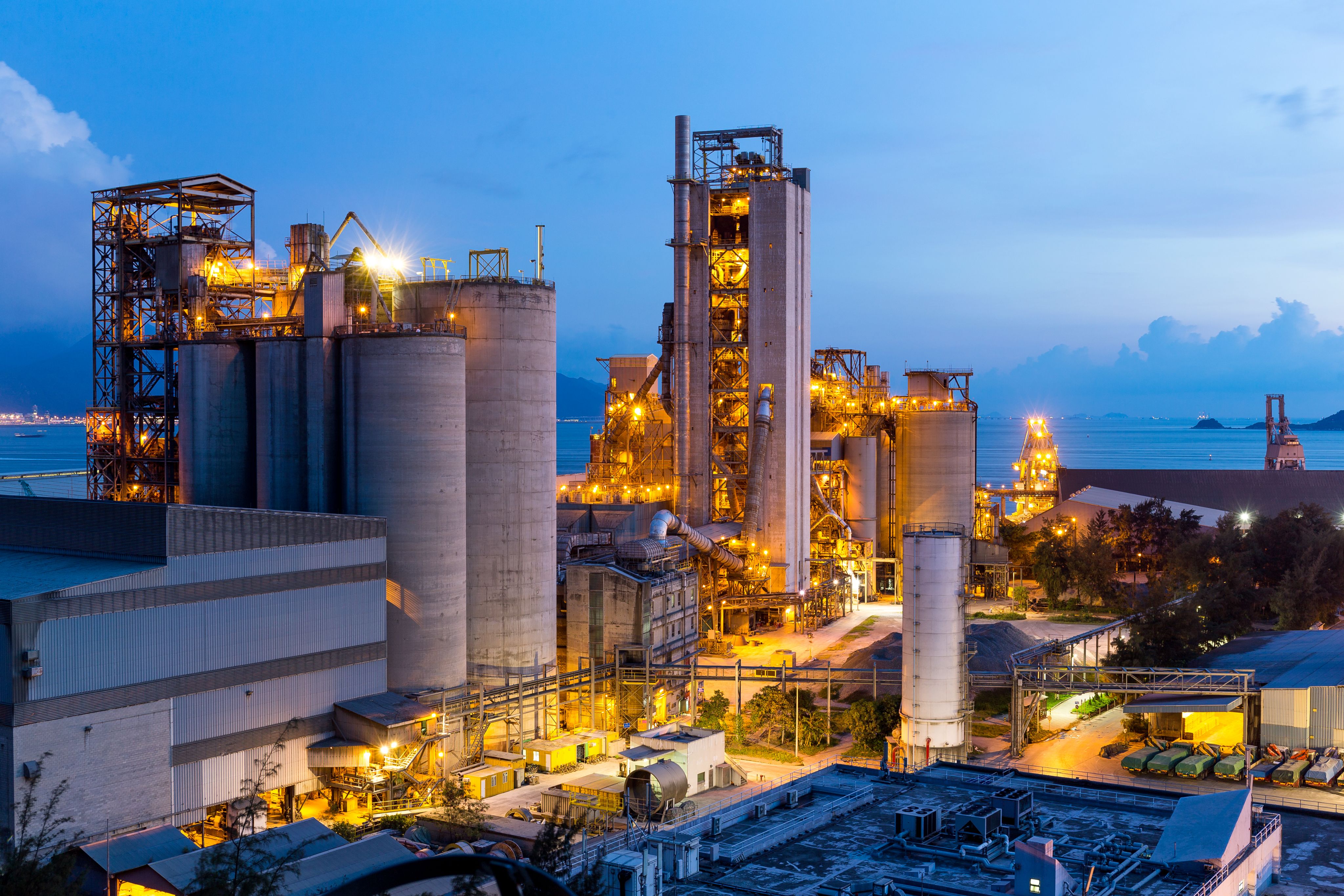
- Chemical & Process Plants
- Manufacturing & Heavy Industry
- Hazardous Material storage facilities
- Automotive & Industrial Campuses

Transportation
Transportation
- Airports & Aviation Facilities
- Metro, Rail & Mass Transit Systems
- Roads, Highways & Vehicular Tunnels
- Ports, Shipyards & Marine Transport Infrastructure

Defence
Defence
- Defence & Command Facilities
- Critical National Infrastructure (CNI)
- Secure & Hardened Assets
- Border, Coastal & Strategic Installations

Infrastructure
Infrastructure
- Data Centres & Digital Infrastructure
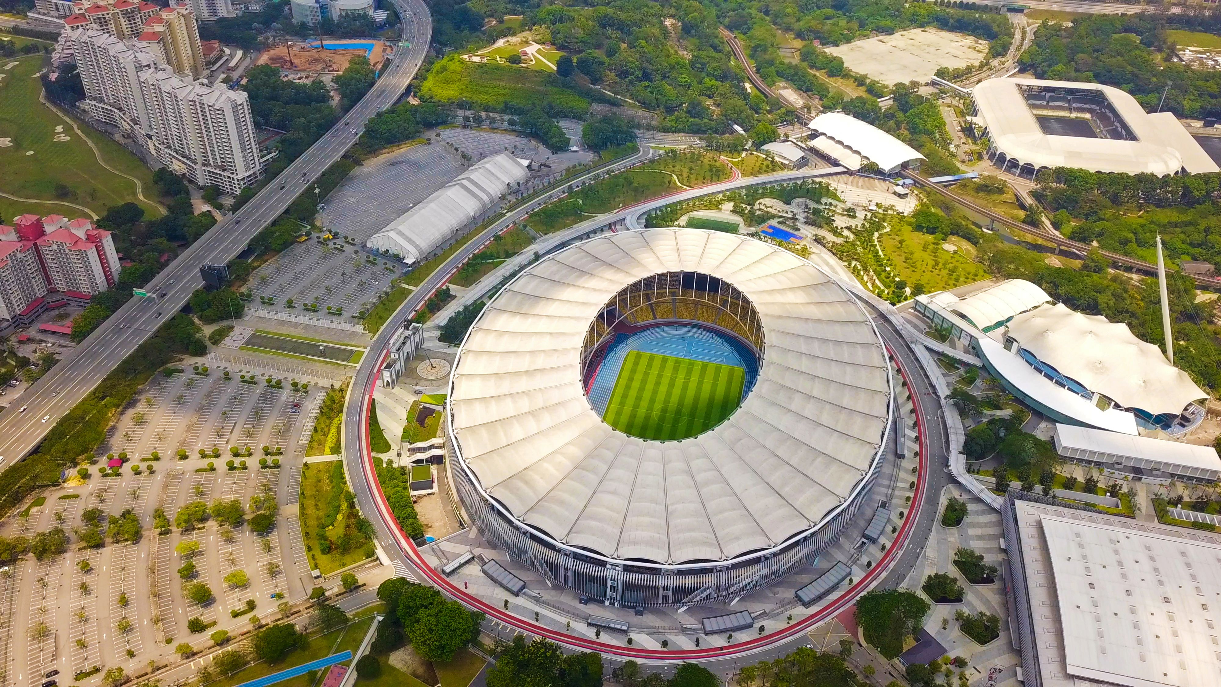
- Public Venues & Stadia
- Cultural & Institutional Buildings
- Government & Diplomatic Facilities
Commercial/Mixed-Use
Commercial/Mixed-Use
- Hospitality & Leisure
- Financial & Commercial Buildings
- Mixed-Use Landmark Developments



Applications for Intake and Exhaust Acoustic Screens
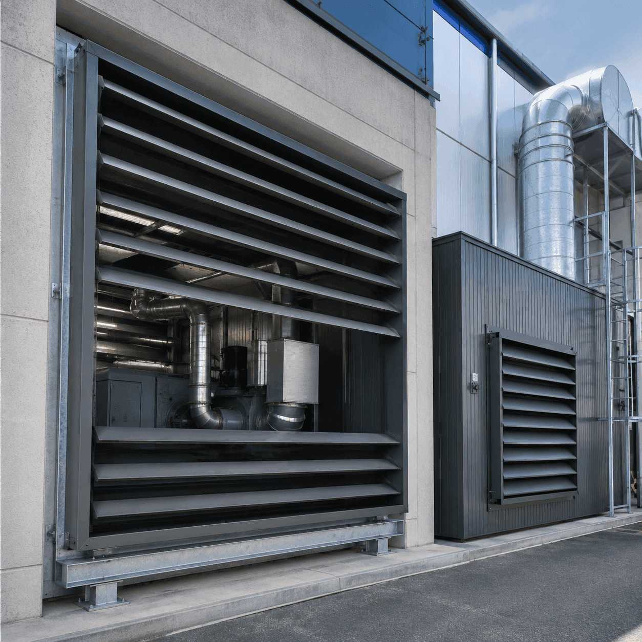
Acoustic screens are considered where an air opening provides a direct path for mechanical or equipment noise and the required ventilation duty must be maintained.
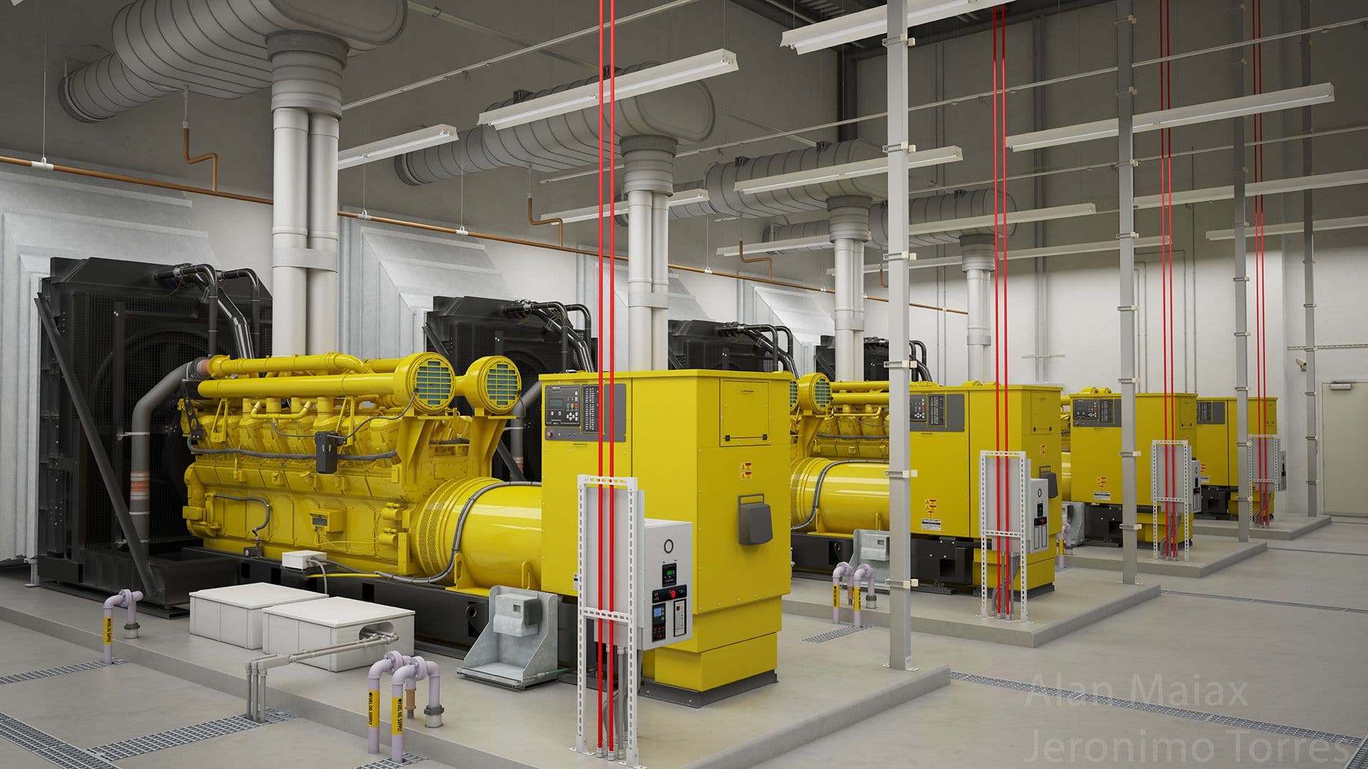
Generator and plantroom ventilation
Mechanical-equipment enclosures
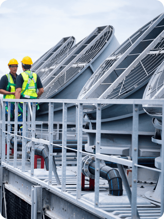
External intake and exhaust openings
Intake and Exhaust Screen Design Considerations
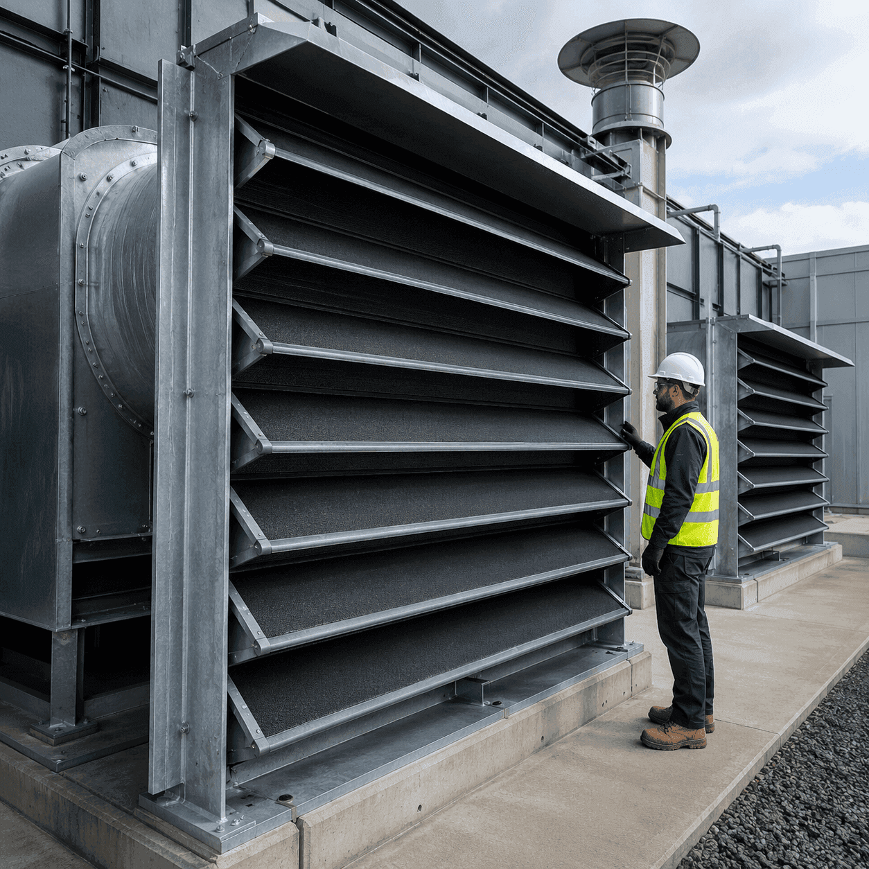
Intake and exhaust screens use similar noise-control principles, but airflow direction, discharge conditions and exposure can change the required arrangement.
Intake conditions
Exhaust conditions
Shared design inputs
What Intake and Exhaust Acoustic Screens Must Address
Evaluate the complete installed system against the project design basis, interfaces and evidence—not as an isolated product selection.
Define the noise spectrum, receptor targets, airflow volume, velocity and allowable pressure drop.
Project risk and purpose
Coordinate screen dimensions, frames, seals, supporting steelwork, weather protection and drainage.
Critical interfaces
Review acoustic, airflow and structural information applicable to the proposed screen geometry.
Evidence-led selection
Inputs for Specifying Intake and Exhaust Acoustic Screens
A clear technical review begins with the performance basis and the conditions the installed system will encounter.
Airflow and pressure-drop criteria
Confirm airflow volume, velocity, direction and allowable pressure drop with the mechanical design.
Noise spectrum and target levels
Provide equipment sound data, receptor locations and the project acoustic criteria.
Opening dimensions and airflow direction
Provide intake or exhaust opening sizes, surrounding construction and available screen depth.
Maintenance and removal access
Confirm wind, rain, corrosion environment, drainage, cleaning and removal requirements.
Frequently Asked Questions About Intake and Exhaust Acoustic Screens
Direct answers to common specification, coordination and evidence questions.
Provide equipment sound data, receptor locations, target noise levels, airflow volume, velocity, direction and allowable pressure drop. Include opening dimensions, available screen depth, weather exposure, structural interfaces and maintenance-access requirements.
Coordinate screen free area and acoustic-path geometry with the mechanical airflow requirement. Frames, seals, opening construction, drainage, filters, dampers and equipment-access zones should be reviewed together before the screen arrangement is confirmed.
Review acoustic and airflow information relevant to the proposed screen geometry, together with structural information for its frames, supports and opening interfaces. General performance data should not be assumed to cover every screen size or arrangement.
They use similar noise-control principles, but the arrangement may differ according to airflow direction, weather exposure, equipment duty, discharge conditions and access requirements.
Yes, where the selected configuration is suitable for the wind, rain, drainage, corrosion and UV conditions at the site. These factors should be included in the structural and material review.
The design should allow inspection, cleaning and removal where needed without obstructing adjacent filters, dampers or equipment. Maintenance needs should be defined before the screen layout is finalised.