

Why Acoustic Attenuation Barrier Wall Protection Matters
Noise from roads, rail corridors, utilities and industrial equipment can affect nearby communities, workplaces and sensitive uses. Effective control requires more than placing a wall between source and receptor. Height, length, continuity, material behaviour, joints, gates, services, foundations and environmental loads all influence the installed outcome.
What is an Acoustic Attenuation Barrier Wall
An acoustic attenuation barrier wall is an engineered system used to control noise transmission between a source and nearby receptors. Its configuration is selected according to the noise spectrum, target criteria, barrier geometry, site exposure and any project-specific safety requirements.

Fire & Safety Compliance
Where the project also requires fire or safety performance, that requirement must be defined and supported for the proposed barrier configuration.

Durability & Weather Resistance
Materials, finishes, supports and foundations are selected for the site's weather, moisture, corrosion and maintenance conditions.

Frequency Range Performance
The acoustic design considers the source spectrum and target conditions rather than relying on a single broad noise value.

Vibration Damping
Supports and interfaces are reviewed for site-specific vibration and structural conditions without assuming universal damping performance.

Sound Absorption
The required balance between sound absorption and transmission control is defined from the acoustic assessment and barrier arrangement.

How the System Reduces Noise Impact
Invicta ANARA coordinates acoustic attenuation barriers around the identified source, nearby receptors and site conditions. Acoustic objectives, structural support, barrier continuity, access and maintainability are considered together before the proposed configuration is finalised.
Barrier height, length, position and continuity are coordinated with the source, receptors and target acoustic criteria.
Materials and finishes are selected for the site's moisture, corrosion, UV and maintenance conditions.
Panels, posts, foundations and connections are coordinated for the barrier geometry and applicable site loads.
Panel sizes and installation sequencing are planned around access and lifting constraints while maintaining barrier continuity.
Appearance and access requirements are considered with the acoustic, structural and environmental design basis.
Performance & Technical Specifications
Acoustic performance
Set target criteria from the project acoustic assessment.
Consider sound transmission and absorption functions required by the application.
Review evidence for the proposed panel arrangement and frequency range.

Barrier continuity
Coordinate joints, edges, returns and transitions.
Detail gates, access points and service crossings.
Avoid unreviewed gaps that create secondary sound paths.

Structural and environmental design
Design supports and foundations for barrier geometry and site loads.
Select materials for moisture, corrosion and UV exposure as applicable.
Coordinate drainage and ground conditions.

Installation and maintenance
Plan panel sizes and lifting around site access.
Inspect alignment, joints and seals during installation.
Maintain access for cleaning, inspection and component replacement.
Engineered Acoustic AttenuationBarriers vs Generic Noise Barriers
Traditional Methods
May not address the project noise spectrum or target receptors.
Gaps at joints, edges and penetrations can create leakage paths.
Structural supports may be designed without sufficient acoustic coordination.
Material exposure and maintenance needs may be considered late.
Engineered Acoustic Attenuation Barrier
Selected around the source, receptors and defined acoustic criteria.
Geometry, joints, gates and interfaces are coordinated as one system.
Structural design reflects barrier dimensions, foundations and site exposure.
Access and material serviceability are planned for the operating environment.
Sectors We Serve
Our solutions are designed for sectors where infrastructure reliability, safety, and long-term performance are critical.

Energy & Utilities

Energy & Utilities
- Power & Grid Infrastructure
- Energy & Process Facilities
- Onshore & Offshore Assets
- Renewable Energy Infrastructure
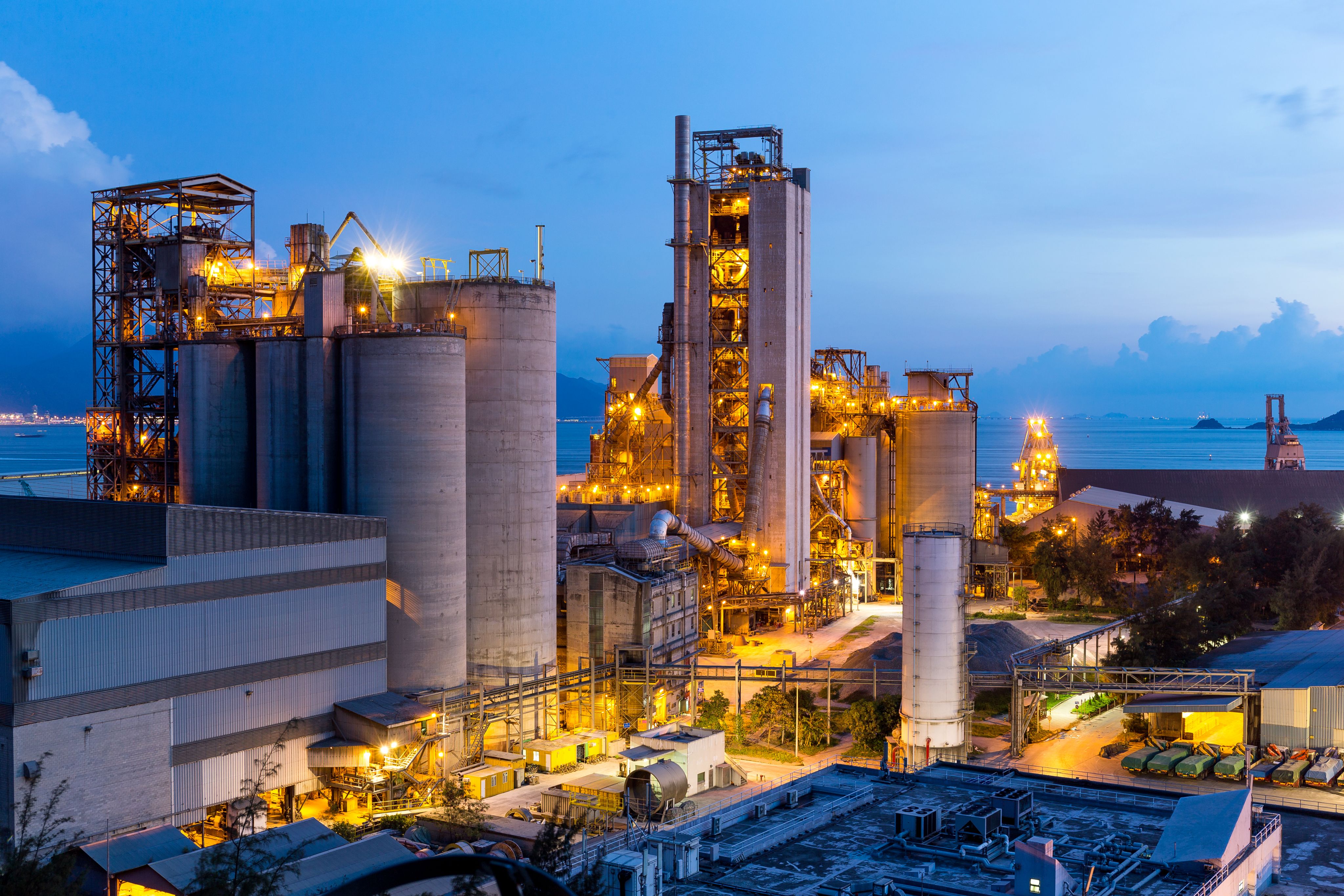
Industrial
Industrial
- Chemical & Process Plants
- Manufacturing & Heavy Industry
- Hazardous Material storage facilities
- Automotive & Industrial Campuses

Transportation
Transportation
- Airports & Aviation Facilities
- Metro, Rail & Mass Transit Systems
- Roads, Highways & Vehicular Tunnels
- Ports, Shipyards & Marine Transport Infrastructure

Defence
Defence
- Defence & Command Facilities
- Critical National Infrastructure (CNI)
- Secure & Hardened Assets
- Border, Coastal & Strategic Installations
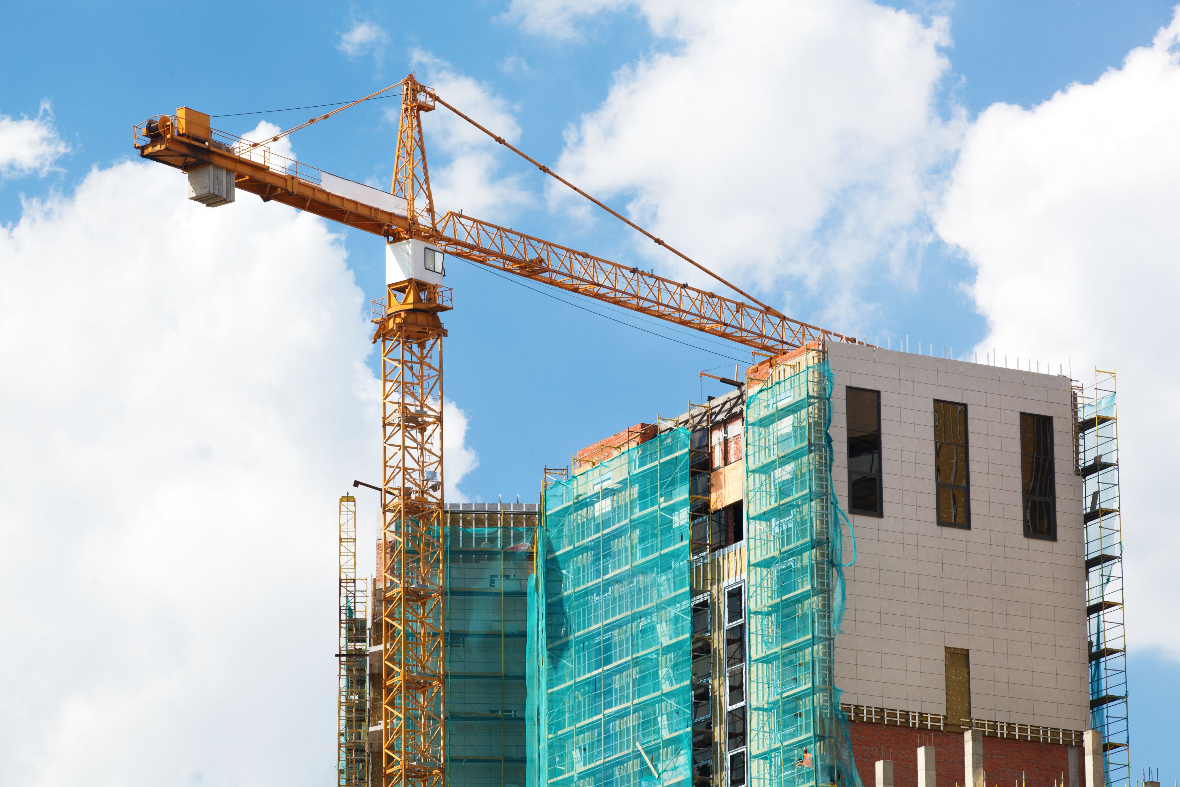
Infrastructure
Infrastructure
- Data Centres & Digital Infrastructure
- Public Venues & Stadia
- Cultural & Institutional Buildings
- Government & Diplomatic Facilities

Commercial/Mixed-Use
Commercial/Mixed-Use
- Hospitality & Leisure
- Financial & Commercial Buildings
- Mixed-Use Landmark Developments



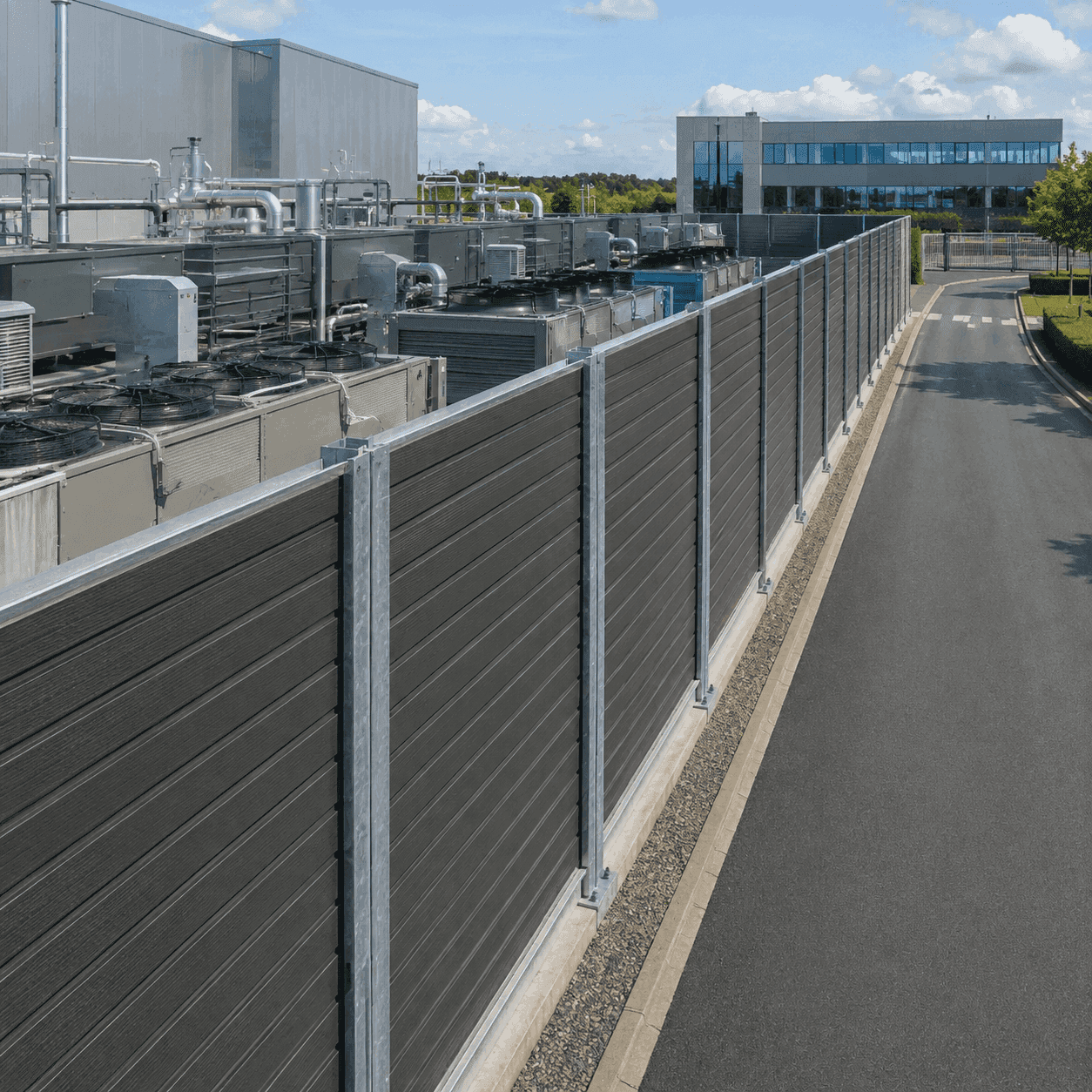
Applications for Acoustic Attenuation Barrier Walls
Barrier walls are considered where a defined noise source affects nearby receptors and the site allows a continuous, structurally supported barrier arrangement.
Road and rail boundaries
Industrial and utility perimeters
Noise-sensitive interfaces
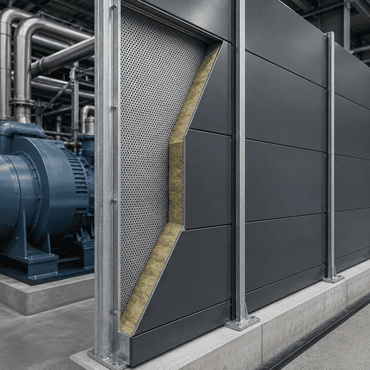
Sound Absorption and Transmission Control
Acoustic barrier design may need to manage sound passing through the wall, sound diffracting around it and sound reflected from its surfaces. The required functions should be defined by the project acoustic assessment.
Transmission through the barrier
Reflection and absorption
Paths around the barrier
What Acoustic Attenuation Barrier Walls Must Address
Evaluate the complete installed system against the project design basis, interfaces and evidence—not as an isolated product selection.
Define the noise source, spectrum, receptors and target criteria before selecting the barrier arrangement.
Project risk and purpose
Coordinate height, length, joints, edges, gates, supports and service crossings.
Critical interfaces
Review evidence applicable to the proposed panels, arrangement, supports and environmental conditions.
Evidence-led selection
Inputs for Specifying Acoustic Attenuation Barrier Walls
A clear technical review begins with the performance basis and the conditions the installed system will encounter.
Target acoustic criteria
Provide the acoustic study, source spectrum and required conditions at identified receptors.
Source and receptor locations
Map equipment or transport noise sources, surrounding uses and available barrier positions.
Barrier geometry and continuity
Confirm height, length, returns, gates, joints and service crossings.
Wind, exposure and foundation conditions
Provide wind criteria, ground conditions, corrosion environment, drainage and maintenance access.
Frequently Asked Questions About Acoustic Attenuation Barrier Walls
Direct answers to common specification, coordination and evidence questions.
Provide the acoustic assessment, source spectrum, receptor locations, target criteria, proposed barrier location and available height and length. Include site exposure, wind conditions, foundation information, gates, service crossings and maintenance-access requirements.
Coordinate the panels with posts, foundations, joints, returns, gates, drainage and service crossings. The acoustic and structural teams should review the complete route so gaps, openings or unsupported interfaces do not weaken the proposed arrangement.
Review acoustic information relevant to the proposed panel arrangement and frequency range, together with structural information for the posts, connections and foundations. Where combined fire performance is required, review evidence applicable to that complete configuration rather than assuming it from a general product statement.
A fire rated acoustic wall may be considered where both acoustic and fire-separation requirements apply. Both forms of performance must be verified for the proposed system configuration rather than assumed from a general description.
Panel joints, edges, returns, gates, foundations, supports and service crossings can affect continuity. Gaps or uncoordinated openings may reduce the intended acoustic result.
A retrofit may be possible after assessing the existing structure, foundations, access, available geometry and service interfaces. The acoustic and structural suitability of the proposed arrangement must be reviewed.